Blog
What Information Should Be Confirmed Before Integrating YIH KUAN’s Gear-Driven CNC Milling Head Modules?
2026.07.28
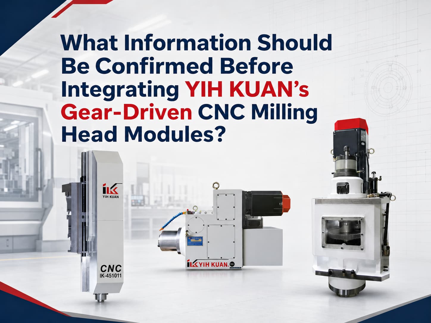
YIH KUAN ENT CO., LTD. provides gear-driven CNC milling head modules for machine tool builders developing new machines, special-purpose machines, and gantry machining equipment. These modules can also be used to upgrade existing CNC machines or replace their milling heads.
One important point should be clarified:
YIH KUAN primarily supplies the mechanical modules of its gear-driven CNC milling heads. Spindle servo motors, servo drives, and CNC controllers are not included.
The spindle motor, drive system, CNC controller, PLC program, and machine wiring are generally selected and integrated by the machine tool builder according to the overall machine design.
Therefore, before selecting a gear-driven CNC milling head, machine tool builders should confirm more than the mounting dimensions. Complete machine and motor information should also be provided so that the suitability of the milling head can be properly evaluated.
YIH KUAN CNC Milling Head Series
YIH KUAN currently offers the following CNC milling head modules:
- IK-451011 CNC Milling Heads
- IK-H4500-A CNC Horizontal Machining Centers Geared Head
- IK-V6000 CNC Vertical Gear Head (2 Speeds)
These three models are designed for gantry, horizontal, and vertical machine configurations. They are suitable for:
- CNC machine tool builders
- Special-purpose machine manufacturers
- Automation system integrators
- Gantry machining equipment
- Existing machine upgrades and milling head replacements
- Custom machining equipment development
What Information Should Be Confirmed Before Integration?
1. Machine Type and Machining Orientation
The first step is to confirm whether the milling head will be installed on:
- A gantry-type machine
- A vertical CNC machine
- A horizontal CNC machine
- A special-purpose machine
- An existing machine being retrofitted
The machining orientation, workpiece dimensions, workpiece material, and primary machining operations should also be specified. These operations may include rough milling, finish milling, drilling, or heavy-duty cutting.
2. Spindle Specifications and Machining Requirements
Different machining conditions require different spindle speeds, torque levels, and motor power. The following information should be confirmed:
- Tool holder specification, such as BT50 or ISO50
- Required maximum spindle speed
- Tool diameter
- Workpiece material
- Cutting depth
- Machining load
- Roughing or finishing requirements
A higher spindle speed or a larger motor is not necessarily better. The milling head should be selected according to the actual machining conditions.
3. Mounting Interface and Available Machine Space
Milling head integration involves more than checking the mounting flange and bolt-hole pattern. The following factors should also be reviewed:
- Mounting surface dimensions
- Mounting hole positions
- Spindle center position
- Overall dimensions of the milling head
- Available space for motor installation
- Tool-changing clearance
- Potential interference with the tool magazine, machine enclosure, workpiece, or fixture
- Maintenance and disassembly clearance
- The weight and moment load that the machine structure can support
Interference checks using assembly drawings or 3D models are recommended during the early stages of machine design. This helps prevent space limitations from being discovered after the machine structure has already been completed.
4. Spindle Servo Motor Information
YIH KUAN's gear-driven CNC milling head modules generally do not include a spindle servo motor. Machine tool builders should therefore provide information about the motor they plan to use, including:
- Motor brand and model
- Rated and peak power
- Rated and maximum speed
- Motor mounting flange dimensions
- Motor shaft diameter
- Keyway dimensions
- Overall motor dimensions
- Encoder specifications
YIH KUAN will use the motor information to evaluate whether the mounting method, transmission interface, and milling head configuration are compatible.
5. CNC Control and Sensor Signals
The CNC controller, servo drive, and PLC program are integrated by the machine tool builder.
Depending on the milling head configuration, the machine control system may need to manage:
- Spindle start and stop
- High- and low-speed gear shifting
- Tool clamping and unclamping
- Spindle orientation
- Sensor signals
- Hydraulic operations
- Safety interlocks
- Alarm handling and reset functions
The machine tool builder should develop a complete control sequence based on the CNC controller and PLC system used in the machine.
6. Hydraulic, Lubrication, and Cooling Conditions
Depending on the CNC milling head configuration, hydraulic power, lubrication, or spindle cooling may be required for gear shifting, tool clamping, tool unclamping, or temperature control. The following conditions should therefore be confirmed in advance:
- Hydraulic pressure and flow rate
- Hydraulic piping connections
- Lubrication method
- Oil cooler capacity
- Available space for piping
- Maintenance and service access
If the piping arrangement is not planned until after machine assembly, it may interfere with the enclosure, slide, or other mechanical components.
Recommended Information for Quotation and Evaluation
To accelerate milling head selection and integration evaluation, machine tool builders are advised to provide:
- Overall machine layout drawings
- Milling head mounting surface and bolt-hole dimensions
- Available installation space
- Spindle center position
- Spindle servo motor brand, model, and dimensions
- CNC controller brand and model
- Tool holder specification and tool-changing method
- Workpiece dimensions and material
- Machining operations, tool diameter, and spindle speed requirements
- Hydraulic, lubrication, and cooling conditions
Conclusion
YIH KUAN provides gear-driven CNC milling head modules for integration by machine tool builders. Its scope primarily covers the milling head body, gear transmission, spindle mechanism, and related mechanical configuration.
The spindle servo motor, servo drive, CNC controller, PLC program, and complete electrical control system must be selected and integrated by the machine tool builder according to the equipment requirements.
For this reason, selecting a CNC milling head should not be based solely on the spindle specification or mounting flange. The machine structure, motor dimensions, machining requirements, tool-changing clearance, sensor signals, hydraulic system, and cooling conditions should all be evaluated together.
Planning a CNC Machine Tool, Special-Purpose Machine, Gantry Machine, or Machine Upgrade?
Provide your machine layout drawings, mounting dimensions, motor specifications, and machining requirements. YIH KUAN can help you evaluate a suitable gear-driven CNC milling head module for your equipment.
Contact Us
